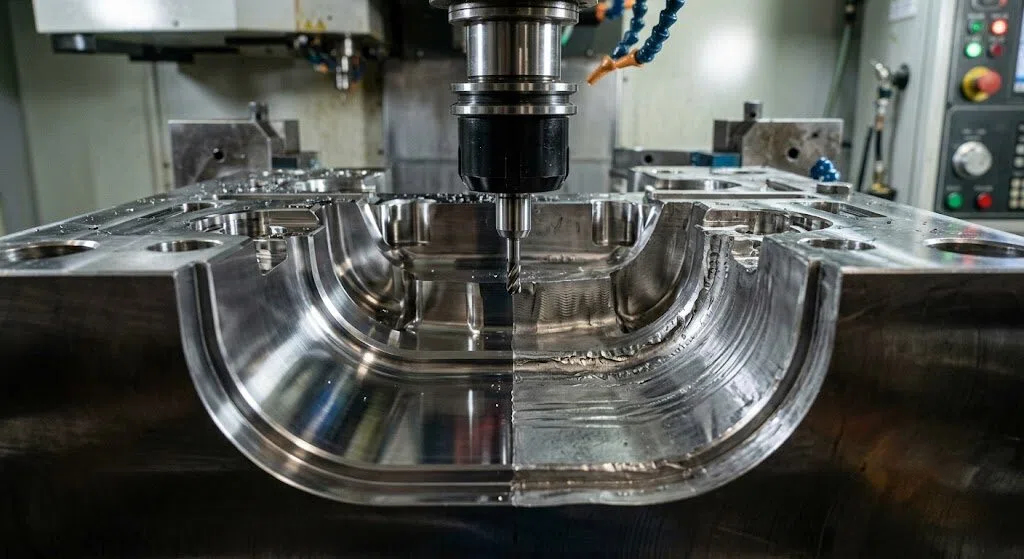
Most issues in P20 Steel Machining don’t come from the material itself. They come from how it is treated on the shop floor—tool choice, cutting strategy, and sequence planning.
In many mold workshops, P20 Steel Machining is assumed to be “easy,” but real production tells a different story: uneven surface finish, unexpected tool wear, and dimensional drift after roughing.
The goal here is not to explain what P20 is. If you need the material background, you can refer to this technical overview of P20 steel properties and applications.
Table of Contents
Why P20 behaves differently during machining (and why shops underestimate it)
One reason P20 Steel Machining is widely misunderstood is its pre-hardened condition. It is usually supplied around 28–32 HRC, which gives a false impression of “easy cutting.”
This is where P20 Steel Machining starts to behave differently from mild steels.
In practical workshops, P20 Steel Machining often shows:
- Built-up edge at moderate speeds
- Rapid flank wear in finishing passes
- Chip welding on carbide tools
These are not material defects. They are process mismatches.
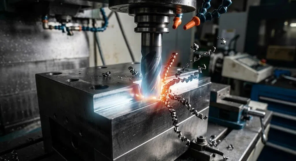
Tool selection decides more than cutting speed
In real P20 Steel Machining, the first failure point is not feed rate—it is tool geometry.
Based on machining guidance from Sandvik Coromant’s technical library

Tool wear is heavily influenced by:
- edge preparation
- coating type
- flute geometry
- tool overhang rigidity
For P20 Steel Machining, many shops still use general-purpose carbide tools designed for mild steel. That leads to unstable cutting conditions even before parameters are adjusted.
A common correction strategy in P20 Steel Machining is:
- switch to fine-grain carbide
- use TiAlN or AlCrN coatings
- reduce tool overhang below 3× diameter
This alone often improves tool life more than any spindle speed adjustment.
Why surface finish problems are usually not “finish problems”
One of the most misunderstood issues in P20 Steel Machining is poor surface quality after finishing passes.
Operators often adjust feed rate or RPM. But in most cases, the real cause is vibration and tool deflection.
In P20 Steel Machining, typical root causes include:
- excessive radial engagement
- long tool overhang
- unstable fixture clamping
- incorrect step-over strategy
In practice, reducing engagement width often improves surface finish more than reducing feed rate.

Cutting strategy matters more than cutting parameters
In most production environments, P20 Steel Machining is done in three stages:
- roughing
- semi-finishing
- finishing
But many shops skip proper semi-finishing, which leads to stress release issues later.
According to the ASM International Handbook of Machining, residual stress redistribution after roughing can directly affect dimensional stability in tool steels
This is especially important in P20 Steel Machining, where pre-hardened structure still contains internal stress from forging and rolling.
A stable workflow usually includes:
- controlled roughing with allowance
- stress relief before finishing
- light finishing pass with stable tool engagement
Without this, P20 Steel Machining often shows size drift after unclamping.
Where machining problems actually start
Most failure analysis in P20 Steel Machining reveals a pattern:
It is not spindle speed
It is not feed rate
It is not coolant
It is sequence and rigidity.
When shops fix these two factors, P20 Steel Machining becomes predictable even without changing machine parameters.
For material behavior, hardness range, and heat treatment response, refer to the full overview of P20 steel here.
Why chatter happens even when feeds and speeds look correct
In real workshop conditions, P20 Steel Machining chatter is rarely caused by incorrect RPM.
Most vibration issues come from structural instability in the cutting system.
Based on machining stability research from the University of Michigan – Manufacturing Engineering Lab, chatter is strongly linked to tool-holder rigidity and dynamic stiffness rather than cutting parameters alone:
In P20 Steel Machining, chatter usually appears in three situations:
- pocket milling with long tools
- side wall finishing with high radial engagement
- thin wall mold structures without support
What matters most is not reducing speed, but controlling cutting load direction.
A stable approach in P20 Steel Machining is:
- reduce radial engagement first (not feed)
- shorten tool overhang
- increase axial depth while reducing radial width
This shift alone often eliminates vibration without touching spindle settings.

Drilling and tapping P20: where most tool failures actually happen
Drilling is often ignored in P20 Steel Machining, but it is one of the highest failure points in production.
The reason is chip evacuation pressure inside pre-hardened steel.
Heat concentration and chip packing are the main causes of drill breakage.
In P20 Steel Machining, drilling problems usually come from:
- using standard HSS drills instead of carbide
- no peck cycle strategy
- insufficient coolant pressure
For tapping:
- use rigid tapping only
- avoid dry tapping in deep holes
- reduce entry speed in blind holes
Once corrected, P20 Steel Machining becomes significantly more stable in hole-making operations.
Tool wear in P20 is predictable if you read the signs early
In advanced P20 Steel Machining, tool wear is not random.
It follows a pattern:
- initial edge rounding
- micro chipping
- flank wear expansion
- sudden failure if ignored
Most failures in P20 Steel Machining come from ignoring early-stage wear signals.
Key indicators:
- slight change in chip color
- increasing spindle load
- loss of surface gloss
Once these appear, tool change timing becomes critical.
Common mistakes in real workshops
In daily P20 Steel Machining, these mistakes appear repeatedly:
- treating P20 like mild steel
- ignoring fixture rigidity
- skipping semi-finishing pass
- over-relying on coolant instead of strategy
- using one tool for roughing and finishing
None of these are parameter issues.
They are process discipline issues in P20 Steel Machining.
Machining strategy checklist (what experienced shops actually do)
A stable workflow in P20 Steel Machining usually looks like this:
- roughing with controlled stock allowance
- stress stabilization pause
- semi-finishing pass
- finishing with reduced radial engagement
- final inspection before polishing
This sequence reduces dimensional drift and improves consistency across batches.
It also explains why experienced mold shops rarely struggle with P20 Steel Machining, even on older CNC machines.
Final takeaway
In practice, P20 Steel Machining is not a material challenge—it is a process control challenge.
Once rigidity, tool selection, and machining sequence are controlled, performance becomes predictable even across different machines and operators.
That is why experienced mold shops rarely “fight the material” during P20 Steel Machining—they control the system around it.
And when that system is stable, P20 Steel Machining stops being a problem and becomes a repeatable production process.
PREGUNTAS FRECUENTES
Is P20 steel difficult to machine?
No. P20 Steel Machining is considered medium-easy, but tool selection and rigidity still matter more than cutting speed.
What is the best tool for P20 machining?
Fine-grain carbide with TiAlN or AlCrN coating performs best in P20 Steel Machining.
Why does surface finish degrade in finishing passes?
Because of tool deflection and vibration, not material hardness in P20 Steel Machining.
Can P20 be machined after heat treatment?
Yes. P20 Steel Machining is typically done in pre-hardened condition, but minor finishing adjustments are possible after heat exposure.
Why does tool life drop suddenly?
Usually due to built-up edge and heat concentration in P20 Steel Machining, not gradual wear.