Table of Contents
I Beams are ubiquitous in structural engineering because their cross-section gives high bending resistance for relatively low material use. Understanding the geometry, load paths and practical limits of the I section helps designers pick the right member for beams, girders and columns.
Section geometry and the concept of second moment of area
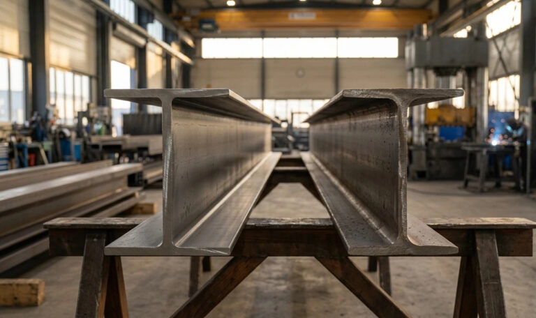
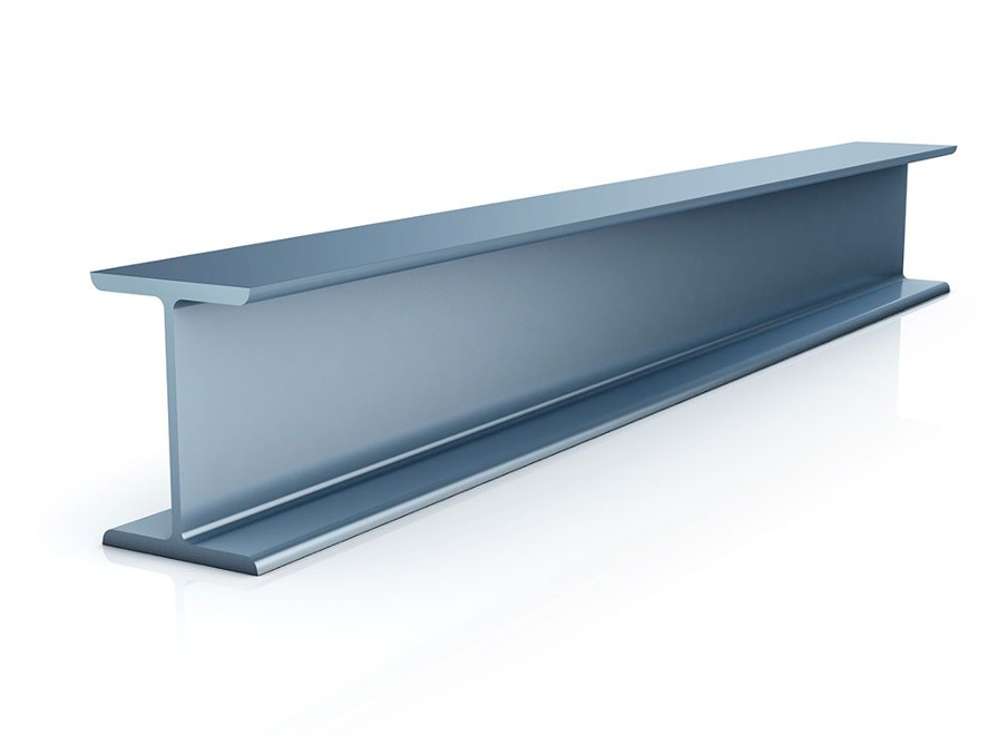
An I section concentrates material in two flanges separated by a slender web. That arrangement maximizes the second moment of area (I), the geometric property most directly related to bending stiffness. When a beam bends, the flanges carry the majority of axial tension and compression while the web carries shear. This separation of functions is why I Beams deliver high bending strength per unit mass.
How bending stress distributes through the section
Under simple bending the highest normal stresses occur at the extreme fibers—top and bottom flanges. The web remains near zero axial stress but must resist transverse shear. In practical design the formula σ = M·y/I describes bending stress; increasing the flange area or flange separation increases I and lowers stress for the same moment. That is the core reason engineers favor I Beams for long spans.
Shear flow, web slenderness and shear buckling
Although flanges carry bending, the web must transmit shear between them. The shear flow q = V·Q/I and the web shear stress τ = V·Q/(I·t) quantify the demand. Narrow thin webs are efficient for weight but risk shear buckling or crippling under concentrated loads. Hence manufacturers optimize web thickness and may add stiffeners. Design checks for I Beams include shear capacity and local buckling limits per recognized standards.
I Beams: lateral-torsional buckling and lateral support needs
When bending causes compression in the top flange, long unsupported members can succumb to lateral-torsional buckling—an instability combining lateral displacement and twist. Bracing at regular intervals, continuous top flanges or using wide-flange variants reduce the unbraced length and raise the available moment capacity. Accounting for lateral support is essential whenever an I Beams span carries significant bending.
Connection detailing and transfer of forces
Connections transfer loads between beams, columns and supporting elements. Welded end-plate, bolted flange, and seated connections are common. Proper detailing ensures flange continuity and adequate shear transfer through the web. The connection design must address block shear, bearing, weld strength and any local reinforcement to keep the I Beams behaving as assumed in analysis.
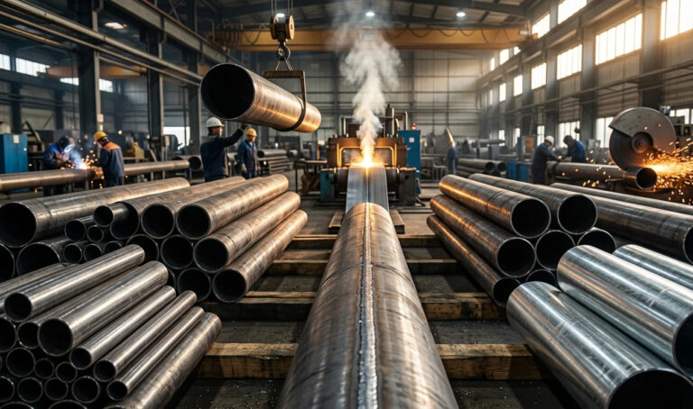
Fabrication, tolerances and residual stresses
Fabrication steps—rolling, straightening, cutting and welding—introduce residual stresses and geometric imperfections in structural members. These affect camber, fit-up and fatigue performance. Controlling tolerances and performing necessary post-weld treatments (stress relieving where required) helps the as-installed I Beams meet both serviceability and strength expectations.
I Beams: serviceability — deflection, vibration and fatigue
Design is not only about strength. Serviceability checks such as deflection limits are critical for user comfort and attached finishes. Members that are lightweight and highly stiff may still vibrate under walking or machinery loads; modal analysis and adding damping or stiffening members are typical remedies. Fatigue checks are required for cyclic loads—weld details and stress concentrations around connections often govern fatigue life for I Beams.
Material choice and corrosion protection
Most structural members of this type are carbon steel, but alloyed steels, weathering steels, or stainless grades are selected for special environments. Protective coatings, hot-dip galvanizing, or cathodic measures extend service life where corrosion is a concern. Coating selection must consider access for inspection, repairability, and compatibility with fire protection systems applied to I Beams.
I Beams: design codes, testing and verification
Engineering practice relies on codes (AISC, Eurocode, AS/NZS, etc.) to select section properties, resistance factors, and buckling curves for these structural members. Physical testing and non-destructive evaluation (NDE) support verification, especially in critical or rehabilitated structures. Always refer to relevant national standards when calculating capacities or detailing connections for I Beams.
I Beams: practical selection checklist for designers
- Identify maximum bending moment, shear and support conditions.
- Choose an I Beams section with adequate I and section modulus S.
- Check shear capacity, local buckling and lateral-torsional buckling.
- Detail connections to avoid premature failures.
- Plan corrosion protection, maintenance access and inspection intervals.
Conclusion: why shape matters for structural efficiency
The efficiency of this structural section comes from geometry that places material where it most effectively reduces bending stress. By separating flange and web roles, it provides a practical balance between strength, stiffness, and economy. Good design practice—honest load assessment, code-based checks, and proper detailing—ensures I Beams perform reliably throughout their service life.
If you want to know more about the relevant content, please click here.